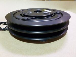
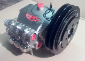
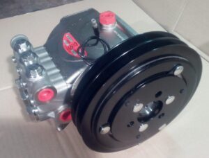
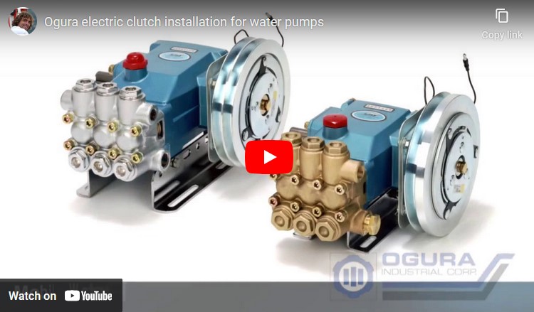
Mobile clutches are made up of three major sub-assemblies.
They are:
Field assembly This is the coil and backing flange which provides the magnetic flux that makes the clutch engage.
Rotor assembly This includes the pulley and the bearing and is normally the input of the clutch.
Armature assembly This includes the armature disc, springs and hub and is normally the output.
The field is mounted to a stationary member such as a support bracket of a pump. The rotor is driven by the belt from the engine and rotates constantly. When the clutch is energized, the armature pulls against the rotor and drives the shaft of the pump.
Engagement of the armature to the rotor is caused by the magnetic attraction between these two elements. The section below shows how the magnetic field is created when direct current is applied to the field. The magnetic flux is transferred from the field into the rotor and then into the armature. The slots in the rotor and the armature are called banana slots. These slots allow the flux to contact the rotor and the armature in more than just two places. [A normal magnet has only two points (north and south) of attraction.] By making multiple points of flux connection, the torque of a clutch can be increased. The picture below shows a standard mobile clutch. It has two flux paths. This is called a double flux, or a four-pole design. To disengage the clutch, the voltage going to the coil is simply turned off. Once the voltage is released, the springs between the armature and the hub pull the armature away from the rotor, creating an air gap so no contact is made.


